Do-It-Yourself Enigma Machine
Encoding/Decoding Tutorial

David Reed
Department of Computer Science
Creighton University
http://dave-reed.com


The following narrative describes the steps involved in encoding the message FOO using the Do-It-Yourself Enigma machine, with initial rotor settings of I-A, III-U, II-D.

1. In the real Enigma machine, the rotors were interchangeable and they could be initially positioned by the operator so that desired letters showed through a window. Thus, to encode a message, the sender and recipient would need to agree upon the initial order of the rotors and their orientations relative to the window. For example, a code book might specify that on a given date, the rotors would be ordered I-III-II from left-to-right, with the letters A, U, and D showing in the window. In short, the rotor settings could be described as I-A, III-U, II-D.

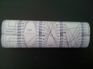
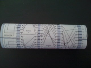
Similarly, the rotors on the DIY Enigma machine can be set to match the desired specifications. The paper loops representing the rotors can be rearranged on the spindle to match the desired rotor order. The rotor window is modeled by a line on the spindle labeled "ROTOR SETTING LINE" and highlighted with up and down arrows. To orient a rotor to a given letter, the paper loop should be rotated on the spindle until the desired letter on the left side of the rotor aligns with the rotor setting line. The picture to the right shows a DIY Enigma machine with initial settings I-A, III-U, II-D.

2. When the operator pressed a key on the real Enigma machine, the first step in the encoding was the rotation of the rotors. Each rotor had a notch, a small peg that connected with adjacent rotors to produce a complicated rotation pattern.

The rotors on the DIY Enigma machine are each labeled with a notch on one of the letters. For example, ROTOR I has a notch (identified by a thick line and the label "notch") at the letter Q. The rotation pattern of the real Enigma machine is modeled by the following rules:

  1. If the notch on either the left or middle rotor is at the rotor setting line, then all three rotors rotate up one position.
  2. If only the rightmost rotor has its notch at the rotor setting line, then the middle and right rotors rotate.
  3. Otherwise, only the right rotor rotates.

In the case of the initial setting, I-A, III-U, II-D, none of the notches are at the rotor setting line, so only the right rotor is rotated, yielding I-A, III-U, II-E.

3. After the rotors on an Enigma machine rotated, an electrical circuit was formed, starting with the key pressed by the user and traversing across the wires embedded in the connected rotors. To make the substitution symmetric, meaning the same settings could be used to encode and decode a message, the Enigma machine utilized a reflector connected to the leftmost rotor. This reflector directed the electrical current back through the rotors until they lit up a light corresponding to the encoded letter.

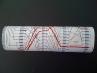
With the DIY Enigma machine, the wiring in the rotors is represented by lines that criss-cross from one side of the rotor to the other. The path taken by the electrical current is tracked by starting at the desired letter on the far right (labeled the INPUT/OUTPUT PANEL) and then following the connected lines across the three rotors, looping around the reflector, back through the rotors, and ending up back at the input/output panel. The picture to the right highlights the encoding of the letter F, with the circuit highlighted in red. The letter F on the input/output panel aligns with the wire labeled B on the right rotor (ROTOR II). This wire aligns with the wire labeled W on the middle rotor (ROTOR III), which similarly aligns with the wire labeled M on the left rotor (ROTOR I). The wire on the left rotor aligns with the wire labeled M on the reflector, which then sends the current back through the rotors from left to right, traveling on wires labeled O, G, and C, respectively. The C wire on the right rotor aligns with the letter L on the input/output panel, so the end result is that F is encoded to be L.

4. Since the notch on the right rotor is at the rotor setting line, the next rotation will result in both the middle and right rotors rotating. This produces the setting I-A, III-V, II-F.
5. The encoding of the second letter, O, follows the circuit from the input/output panel, to the N wire on ROTOR II, the H wire on ROTOR III, the O wire on ROTOR I, the M wire on the reflector, the M wire on ROTOR I, the X wire on ROTOR III, the U wire on ROTOR II, and finally C on the input/output panel. Thus, the letter O is encoded to be C.
6. Since the notch of the middle rotor is at the rotor setting line, the next rotation will result in all three rotors rotating. This produces the setting I-B, III-W, II-G.
7. The encoding of the third letter, O, follows the circuit from the input/output panel, to the P wire on ROTOR II, the L wire on ROTOR III, the X wire on ROTOR I, the V wire on the reflector, the W wire on ROTOR I, the I wire on ROTOR III, the A wire on ROTOR II, and finally U on the input/output panel. Thus, the letter O is encoded to be U.

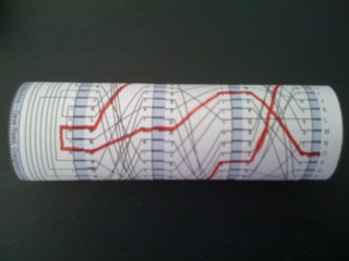
The end result of this process is that the text FOO is encoded as LCU by the DIY Enigma machine with initial settings I-A, III-U, II-D. The same settings will work to decode LCU, recovering the original text FOO.